Hi
I noticed that the dae file could be used for the mesh in Gazebo. Does anybody know where could I find the segway rmp 100 dae files?
Thank you in advance!
↧
dae file for Gazebo mesh
↧
Viewing a .vtk file in rviz
Hello Everyone,
I created a mesh file of .vtk format through the fast triangulation method in the point-cloud library. I want to visualize the .vtk file in rviz. Any thoughts on this?. Please let me know.
↧
↧
Creating a CollisionObject from a mesh in Hydro
I'm trying to create create a collision object from a [mesh resource](http://moveit.ros.org/doxygen/namespaceshapes.html#af2fafa8168f92f2ed5c9ae3748d0f032) and am having trouble understanding how to pass an enumerated type to a message constructor:
const shapes::Mesh* navstar_shape = shapes::createMeshFromResource("package://altius_arm/meshes/NAVSTAR_GPS_Satellite.dae");
shape_msgs::Mesh navstar_mesh;
shapes::constructMsgFromShape(navstar_shape,navstar_mesh);
navstar_collision_object.meshes[0] = navstar_mesh;
I get the following compiler error:
/home/peter/ros/altius_ws/src/altius_arm/src/servo_capture.cpp: In constructor ‘ServoCapture::ServoCapture()’:
/home/peter/ros/altius_ws/src/altius_arm/src/servo_capture.cpp:77:61: error: invalid initialization of reference of type ‘shapes::ShapeMsg& {aka boost::variant>, shape_msgs::Mesh_>, shape_msgs::Plane_>>&}’ from expression of type ‘shape_msgs::Mesh’
/opt/ros/hydro/include/geometric_shapes/shape_operations.h:62:6: error: in passing argument 2 of ‘bool shapes::constructMsgFromShape(const shapes::Shape*, shapes::ShapeMsg&)’
I thought constructMsgFromShape was asking for the message object by reference, but it didn't work so I tried passing it by address which at least gets the compiler to realize that I'm passing the right typedef but gives a similar error. Does anyone have any idea what I'm doing wrong?
↧
Can material colors be applied to Collada (.dae) meshes?
Hello,
I have both STL and Collada (.dae) versions of several meshes (Dynamixel servos and brackets) and I can view both in RViz when used in the URDF file for my robot. However, the material colors I specify for the meshes appear only when using the STL versions of the meshes. When using the Collada (.dae) versions, all meshes appear white regardless of the material or color tags I use in the URDF file. Does one have to specify the material or color differently when using Collada meshes?
P.S. You may ask why I don't just use the STL files and it is because on one of my machines there is a graphics driver bug that prevents the STL meshes from appearing in RViz but the Collada versions appear fine, although without the colors.
UPDATE:
I have figured out a work-around in the meantime: First I imported the TurtleBot's kinect.dae file into Blender, then I imported the AX-12 STL file, and finally, I copyied the material from the Kinect object to the AX-12 object. Then I deleted the Kinect object and exported the AX-12 as a Collada file. At least now I have black servos in RViz!
↧
trouble loading .stl as mesh into RVIZ
I'm trying to load a .stl file as a mesh in RVIZ and having problems seeing anything. I have tweaked the rviz marker tutorial(http://wiki.ros.org/rviz/Tutorials/Markers%3A%20Basic%20Shapes) to attempt to display a binary .stl file from a local directory (~/catkin_ws/src/my_package/stl/mesh.stl). My code looks like this:
#include
#include
int main( int argc, char** argv )
{
ros::init(argc, argv, "basic_shapes");
ros::NodeHandle n;
ros::Rate r(1);
ros::Publisher marker_pub = n.advertise("visualization_marker", 1);
while (ros::ok())
{
visualization_msgs::Marker marker;
// Set the frame ID and timestamp. See the TF tutorials for information on these.
marker.header.frame_id = "/my_frame";
marker.header.stamp = ros::Time::now();
// Set the namespace and id for this marker. This serves to create a unique ID
// Any marker sent with the same namespace and id will overwrite the old one
marker.ns = "basic_shapes";
marker.id = 0;
// Set the marker type
marker.type = visualization_msgs::Marker::MESH_RESOURCE;
// Set the marker action. Options are ADD and DELETE
marker.action = visualization_msgs::Marker::ADD;
// Set the pose of the marker. This is a full 6DOF pose relative to the frame/time specified in the header
marker.pose.position.x = 0;
marker.pose.position.y = 0;
marker.pose.position.z = 0;
marker.pose.orientation.x = 0.0;
marker.pose.orientation.y = 0.0;
marker.pose.orientation.z = 0.0;
marker.pose.orientation.w = 1.0;
// Set the scale of the marker -- 1x1x1 here means 1m on a side
marker.scale.x = 1.0;
marker.scale.y = 1.0;
marker.scale.z = 1.0;
// Set the color -- be sure to set alpha to something non-zero!
marker.color.r = 0.0f;
marker.color.g = 1.0f;
marker.color.b = 0.0f;
marker.color.a = 1.0;
marker.lifetime = ros::Duration();
// Publish the marker
marker.mesh_resource = "package://my_package/stl/mesh.stl";
marker_pub.publish(marker);
r.sleep();
}
}
I'm pretty sure the line **marker.mesh_resource = "package://my_package/stl/mesh.stl";** is my problem. Any help is greatly appreciated!
Thanks!
↧
↧
Cannot load Mesh Marker in ros3djs
Continuation from [here](https://github.com/RobotWebTools/ros3djs/issues/68)
Attempting to load a mesh marker in the browser results in the following errors:
XMLHttpRequest cannot load file:///pr2_description/meshes/base_v0/base.dae. Cross origin requests are only supported for HTTP. index.html:1
Uncaught NetworkError: Failed to execute 'send' on 'XMLHttpRequest': Failed to load 'file:///pr2_description/meshes/base_v0/base.dae'. ColladaLoader2.min.js:1
**Edit**:
The above error message occurs when trying to access `file:///home/dlu/.../index.html`. Accessing `http://localhost/.../index.html` results in the following error.
Failed to load resource: the server responded with a status of 404 (Not Found) http://localhost/pr2_description/meshes/base_v0/base.dae
As noted on the linked page, the mesh_resource given is ` "package://pr2_description/meshes/base_v0/base.dae"`.
↧
Import scene model into RVIZ/MoveIt
Hi all,
I am wanting to launch RVIZ and have it import laboratory environment into the planning scene.
I have a 3D model of the lab in SolidWorks and available as an STL.
How can I do this? Are there any parameters i can load this into?
Cheers
↧
Creating a better mesh
Hi,
I wanted to create mesh of household objects, so that I can later recreate the household scene in Gazebo. I want to use kinect and think that interactively, it can be done quite easily. My exact problem:
After capturing the scene using kinect, I am able to filter out chair, the front view of the chair looks: 
However when I am trying to create a mesh from it (using PCL, tutorial at: http://pointclouds.org/documentation/tutorials/greedy_projection.php#greedy-triangulation I am not able to set optimal size of triangles. My mesh looks like:

I need a smooth mesh. As if a low pass filter is passed on it. How can I achieve that.
Any help or pointer is greatly appreciated.
↧
Unable to combine MLS and mesh generation in one file
Hi,
I am able to do MLS and then also generate mesh, but I need to do both of them separately. I am not able to find a way to do it in one go. First I do MLS and save the file. And then read that file again and generate mesh.
If I combine both I am encountering segmentation fault. The code does MLS successfully but than fails.
The two tutorials which I tried to combine are:
Greedy projection : http://pointclouds.org/documentation/tutorials/greedy_projection.php#greedy-triangulation
and
MLS : http://pointclouds.org/documentation/tutorials/resampling.php#moving-least-squares
Also since MLS itself compute the surface normal so I commented the part of the code where normal are generated.
Any help of pointers is greatly appreciated.
Let me know if I ask PCL related questions somewhere else?
My combined code is:
int
main (int argc, char** argv)
{
  ros::init(argc, argv, "seg");	//is the third param node name
  ros::NodeHandle nh;
  int p_setKSearch = 20;
  double p_setSearchRadius = 0.025;
  double p_setMu = 2.5;

  double p_neighbours = 100;
  double p_maxSurfAnglePiDiv = 4; // 45 degrees
  double p_minAnglePiDiv =18; // 10 degrees

  double p_maxAnglePiDiv = 1.5; // 120 degrees
  bool p_normal_consist = false;
  std::string p_pcd_file = "/home/aknirala/chair.pcd";

  double lDv;	//Loaded double value
  int lIv;
  bool lBv;
  std::string lSv;

  std::cout<<"\n Getting the parameters...............";
  if(nh.getParam("/mesh/meshParam/p_setKSearch", lIv))	  		p_setKSearch = lIv;
  if(nh.getParam("/mesh/meshParam/p_setSearchRadius", lDv))	  	p_setSearchRadius = lDv;
  if(nh.getParam("/mesh/meshParam/p_setMu", lDv))	  			p_setMu = lDv;

  if(nh.getParam("/mesh/meshParam/p_neighbours", lDv))	  		p_neighbours = lDv;
  if(nh.getParam("/mesh/meshParam/p_maxSurfAnglePiDiv", lDv))	p_maxSurfAnglePiDiv = lDv;
  if(nh.getParam("/mesh/meshParam/p_minAnglePiDiv", lDv))	  	p_minAnglePiDiv = lDv;

  if(nh.getParam("/mesh/meshParam/p_maxAnglePiDiv", lDv))	  	p_maxAnglePiDiv = lDv;
  if(nh.getParam("/mesh/meshParam/p_normal_consist", lBv))	  	p_normal_consist = lBv;
  if(nh.getParam("/mesh/sourceFile", lSv))	  	p_pcd_file = lSv;

  std::cout<<"\n p_setKSearch : "<<p_setKSearch;
  std::cout<<"\n p_setSearchRadius : "<<p_setSearchRadius;
  std::cout<<"\n p_setMu : "<<p_setMu;

  std::cout<<"\n p_neighbours : "<<p_neighbours;
  std::cout<<"\n p_maxSurfAnglePiDiv : "<<p_maxSurfAnglePiDiv;
  std::cout<<"\n p_minAnglePiDiv : "<<p_minAnglePiDiv;

  std::cout<<"\n p_maxAnglePiDiv : "<<p_maxAnglePiDiv;
  std::cout<<"\n p_normal_consist : "<<p_normal_consist;
  std::cout<<"\n p_pcd_file : "<<p_pcd_file;

  // Load input file into a PointCloud<T> with an appropriate type
  pcl::PointCloud<pcl::PointXYZ>::Ptr cloud (new pcl::PointCloud<pcl::PointXYZ>);
  pcl::PCLPointCloud2 cloud_blob;
  pcl::io::loadPCDFile (p_pcd_file, cloud_blob);
  pcl::fromPCLPointCloud2 (cloud_blob, *cloud);		//What exactly is being converted here?
  	  	  	  	  	  	  	  	  	  	  	  	  	 //cloud_blob may not be of type XYZ :-)
  //* the data should be available in cloud
  //Convert a PCLPointCloud2 binary data blob ---> into a pcl::PointCloud<T> object
  //Oh, so this is one of the way to load any point cloud type from a pcd file, which we do not
  // know before reading the file to desired point type. IN this case, to PointXYZ.


  /*
  // Normal estimation*
  pcl::NormalEstimation<pcl::PointXYZ, pcl::Normal> n;
  pcl::PointCloud<pcl::Normal>::Ptr normals (new pcl::PointCloud<pcl::Normal>);
  pcl::search::KdTree<pcl::PointXYZ>::Ptr tree (new pcl::search::KdTree<pcl::PointXYZ>);
  tree->setInputCloud (cloud);
  n.setInputCloud (cloud);
  n.setSearchMethod (tree);
  n.setKSearch (p_setKSearch);		//It was 20
  n.compute (*normals);				//Normals are estimated using standard method.
  //* normals should not contain the point normals + surface curvatures

  // Concatenate the XYZ and normal fields*
  pcl::PointCloud<pcl::PointNormal>::Ptr cloud_with_normals (new pcl::PointCloud<pcl::PointNormal>);
  pcl::concatenateFields (*cloud, *normals, *cloud_with_normals);
  //* cloud_with_normals = cloud + normals


*/


  //Here Normals are being generated and then merged. But MLA (moving least square) can do that in one go.
  pcl::search::KdTree<pcl::PointXYZ>::Ptr tree (new pcl::search::KdTree<pcl::PointXYZ>);

  // Output has the PointNormal type in order to store the normals calculated by MLS
   pcl::PointCloud<pcl::PointNormal> mls_points;

   // Init object (second point type is for the normals, even if unused)
   pcl::MovingLeastSquares<pcl::PointXYZ, pcl::PointNormal> mls;

   mls.setComputeNormals (true);

   // Set parameters
   mls.setInputCloud (cloud);	//of type xyz
   mls.setPolynomialFit (true);
   mls.setSearchMethod (tree);
   mls.setSearchRadius (p_setSearchRadius);		//original was 0.03

   // Reconstruct
   mls.process (mls_points);

   std::cout<<"\n MLS constructed.";
   pcl::io::savePCDFile ("bun0-mls.pcd", mls_points);
   std::cout<<"\n MLS written.";


   pcl::PointCloud<pcl::PointNormal>::Ptr mls_points_ptr (&mls_points);

   // Create search tree*
   pcl::search::KdTree<pcl::PointNormal>::Ptr tree2 (new pcl::search::KdTree<pcl::PointNormal>);
   tree2->setInputCloud (mls_points_ptr);

  // Initialize objects
  pcl::GreedyProjectionTriangulation<pcl::PointNormal> gp3;
  pcl::PolygonMesh triangles;

  // Set the maximum distance between connected points (maximum edge length)
  gp3.setSearchRadius (p_setSearchRadius);			//It was 0.025

  // Set typical values for the parameters
  gp3.setMu (p_setMu);											//It was 2.5
  gp3.setMaximumNearestNeighbors (p_neighbours);	//It was 100
  gp3.setMaximumSurfaceAngle(M_PI/p_maxSurfAnglePiDiv); // 45 degrees	//it was 4
  gp3.setMinimumAngle(M_PI/p_minAnglePiDiv); // 10 degrees		//It was 18
  gp3.setMaximumAngle(M_PI/p_maxAnglePiDiv); // 120 degrees		//it was 1.5
  gp3.setNormalConsistency(p_normal_consist);					//It was false

  // Get result
  gp3.setInputCloud (mls_points_ptr);
  gp3.setSearchMethod (tree2);
  gp3.reconstruct (triangles);

  // Additional vertex information
  std::vector<int> parts = gp3.getPartIDs();
  std::vector<int> states = gp3.getPointStates();
  pcl::io::saveVTKFile ("/home/aknirala/mesh_Smooth.vtk", triangles);
  // Finish
  return (0);
}
↧
↧
Creating custom Gazebo world files from sdf's/dae's for use with roslaunch
Hi,
I have been trying to figure this out for a couple of days now and am having trouble. Basically I want to create a world file to be launched via roslaunch that is composed of number of model sdf's that reference local meshes from within my package (e.g., file://mesh_name.dae
↧
scale tag in uwsim
Hello,
I want to use scale tag for my mesh file in urdf that is loaded in uwsim, i tried like standard urdf in mesh tag, but it doen't work, also tried with inside collision tag that i got parsing error. anybody knows how it is possible to scaling mesh files in urdf for uwsim?
Also is it possible to use xacro in uwsim or not?
Thanks in advance.
my urdf:
↧
ROS indigo rviz OGRE mesh wrong lighting
Hi All,
i got another issue with the ROS rviz plugin while moving from hydro to indigo version. I wrote a rviz-plugin which loads and display a ogre mesh (a vehicle to be more exact). In ROS hydro everything is the more or the less fine, the mesh is drawn as it should and also the lighting is correct.
If i change nothing in the plugin and only change the ROS version to indigo, some really strange things happen:
1. The lighting of the mesh seams to be broken, nearly all surfaces are drawn black.
2. The mesh seams to be drawn twice. I tried to add a GLSL shader program which adds a simple phong-shading to some surfaces / materials. Despite of that the model and view matrix will not get passed correctly to the shader (i used the auto params) i got some heavy z-fighting on surfaces which definitely are not modeled double sided.
What i already tried / did:
1. Double checked normals, they are ok.
2. Viewed the model with the Ogre Max Viewer, which also uses OGRE Version 1.8.1 (same as the ROS indigo) - Lighting is correct!
3. Wrote a simple test program which not uses ROS. - Lighting is correct!
4. Updated mesh with the Update Utility of OGRE.
5. Tested another mesh - Same issue!
6. Programmatically changed Face Culling, Light, various material values of the mesh, use own GLSL shader (see above) Nothing changed. ( Set ambient light in scene-manager, add additional light to scene ... )
7. Exported a simple cube from Blender (start scene cube) 2.69.0 with blender2ogre-0.6.0 and tested this mesh in both ROS versions. Same here, Cube is black in ROS indigo and white (correct lighting) in ROS hydro. Both with identical rviz plugin.
8. Cloned newest rviz version (indigo-devel-branch) to ROS-hydro version so rviz 1.11.3 will run under ROS-hydro, everything works well! I also tested the old rviz version 1.10.18 (hydro-devel-branch) under ROS-indigo, lighting still broken. **So it seems that the new Ogre-Version 1.8.1 is the cause of this problem, or maybe a not correctly adapted rviz.**
What seems to work:
1. Emissive materials seems to work in ROS indigo. The cube will be red if emissive set to 1 0 0 1 in ogre-material file.
Did someone of you encounter the same problems drawing OGRE Meshes in ROS-indigo-rviz?
Mesh in ROS Hydro:
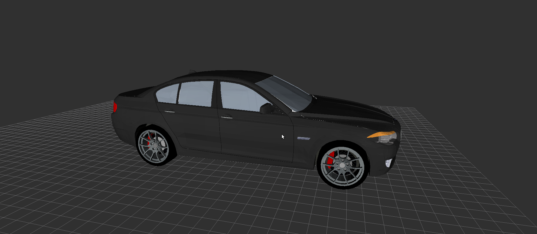
Mesh in ROS Indigo:

↧
RViz ignores COLLADA mesh colours
I have a COLLADA (.dae) file that I have exported from blender. Its just a cube that has been shaded green.
However, whenever I try to get rviz to display this mesh (using a Marker display) all I get is a white cube.
I have set the marker colours to RGBA = {0, 0, 0, 0} in the message. I have set /mesh_use_embedded_materials to true. I read somewhere that if there is an ambient colour in the mesh file with one of its components set to 0 that rviz wont render it properly, I checked that and there were no zeros.
[This link](https://www.dropbox.com/sh/y2lbr0cn5ul8jy0/AAD24vtkl2DpPrt-KOsFO740a?dl=0) has the mesh file and screenshots from blender and rviz.
Can someone tell me how to get rviz to render my mesh using the coulours specified in the mesh file?
I am using the lastest version of Blender (2.72, downloaded just the other day). I am running Ubuntu 14.04 and ROS Indigo 1.11.9
Bidski
↧
↧
Creating stl mesh file with textures
Hello,
I'm trying to make a simple cube to set over a pioneer. The cube has some Aruco Tags (textures). I did the cube in sketchup and them exported it to stl. Then I saved it with meshlab and put it in my robot.
Problem--> the cube doesn't have the textures (Arucos tags) I put in sketchup. How do you export the file with the textures included anyone knows?
↧
Mesh .dae file with textures invisible
I created a file .dae with sketchup of a cube with Textures.
I want to put the cube over a pioneer but when I see the robot in Rviz the cube is transparent.
Should I stop using sketchup to generate the .dae and try some other program? Need some help here.
↧
How to add a Mesh to PlanningScene in Python
Hi,
I'm having trouble adding a Mesh I've created in Blender (.stl file) to my Planning Scene, which is visualized in Rviz.
It's supposed to be the floor the robot is standing on.
I'm using Python.
Here is the relevant part in my code:
def addPlanningScene():
# Use the planning scene object to add or remove objects //Interface
scene = moveit_commander.PlanningSceneInterface()
REFERENCE_FRAME = '/world'
p = PlanningScene()
p.is_diff = True
# Create a scene publisher to push changes to the scene //PlanningScene
scene_pub = rospy.Publisher('/move_group/monitored_planning_scene', PlanningScene)
# Give each of the scene objects a unique name
Ground_id = 'ground'
Object1_id = 'box1'
Object2_id = 'box2'
# Remove leftover objects from a previous run
scene.remove_world_object(Ground_id)
scene.remove_world_object(Object1_id)
scene.remove_world_object(Object2_id)
scene.remove_world_object(target_id)
pose_Ground = geometry_msgs.msg.PoseStamped()
pose_Ground.header.frame_id = REFERENCE_FRAME
pose_Ground.pose.position.x = 0.0
pose_Ground.pose.position.y = 0.0
pose_Ground.pose.position.z = -0.05
scene.add_mesh(Ground_id,pose_Ground,'./Scene_Mesh/Ground_Plane.stl')
scene_pub.publish(PlanningScene)
I'm trying to use the the add_mesh function from the [planning_scene_interface.py](https://github.com/ros-planning/moveit_commander/blob/indigo-devel/src/moveit_commander/planning_scene_interface.py)
It should be an easy problem to solve but I'm stuck right now.
Appreciate any Help! Thanks.
↧
rosjava build app RVIZ FOR ANDROID
Hi!
i am having some problems with RVIZ-FOR-ANDROID APP.
the first problem came when i try to compile the application with the any change that i want to make.
i download the source from https://bitbucket.org/zimmrmn3/rviz-for-android/downloads
In this repository i have the .apk file that run perfectly on my tablet, but i need to make some change because i am having problems when i need to simulate a mesh type shape.
I am using android-sdk, so the first thing that i have made it was import project. The main problem is that i don't know what i have to do know.. i can't run the app from android-studio. I thougth that i don't have linked rosjava and my app... but when i try to compile the app it appear the follow error:
* What went wrong:
Could not resolve all dependencies for configuration ':android_gingerbread_mr1:compile'.
> Could not resolve group:ros.rosjava_core, module:rosjava, version:0.0.0-SNAPSHOT.
Required by:
ros.android_core:android_gingerbread_mr1:0.0.0-SNAPSHOT> Could not GET 'http://robotbrains.hideho.org/nexus/content/groups/ros-public/ros/rosjava_core/rosjava/0.0.0-SNAPSHOT/maven-metadata.xml'.
* Try:
Run with --stacktrace option to get the stack trace. Run with --info or --debug option to get more log output.
BUILD FAILED
And my second problem came with the .apk that provides in the URL. Do you know why i can't see my meshes on my visualization? the connection is working perfectly.. all my pointsCould are visualized and the tf... but the geometries that aren't defined by box, cylinder or spheres. the meshes that are defined for a .dae file it's impossible to visualize..
someone have a answer?
thanks very much!
↧
↧
Mesh Marker in ros3djs - 404 error
I'm trying to display the PR2 using ros3djs, using 'http://resources.robotwebtools.org/' as the path to resources.. However, I'm getting a bunch of errors from STLLoader.js in the form of:
GET http://resources.robotwebtools.org/pr2_description/meshes/base_v0/caster.stl 404 (Not Found)
Uncaught InvalidStateError: Failed to read the 'responseText' property from 'XMLHttpRequest': The value is only accessible if the object's 'responseType' is '' or 'text' (was 'arraybuffer').
(weirdly enough, the robot is still displayed)
Is there something wrong with my settings, or is the mesh hosting just down? Is there a way to find out?
↧
load mesh to rviz and "publish current scene" no effect MoveIt!
When I work with MoveIt!, instead of loading objects from the tabs in Rviz GUI, I loaded a mesh model into rviz using C++ code (visualization marker) and the loading was successful, I can see the object was there in Rviz. But after I clicked "publish current scene" the planning scene did not take into account the object in terms of collision detection and path planning. Could anyone shed light on how I can make sure the planning scene is aware of the loaded object? Thanks!
↧
Unable to display Mesh as an interactive marker
I want to use a mesh as a marker.
To do that, I changed [basic_controls.py](https://github.com/ros-visualization/visualization_tutorials/blob/indigo-devel/interactive_marker_tutorials/scripts/basic_controls.py) to :
marker.type = Marker.MESH_RESOURCE;
marker.mesh_resource = 'package://HexagonalPrism.STL'
(And added a `from visualization_msgs.msg import *` at the top as well)
I get the following error
Error retrieving file [package://HexagonalPrism.STL]: Could not parse package:// format into file:// format
RViz screenshot : https://drive.google.com/file/d/0B-PFIKJ4nKIuMVdzd3AtekNXYUk/view?usp=sharing
The same works fine if I do a simple marker:
marker = visualization_msgs.msg.Marker()
marker.type = visualization_msgs.msg.Marker.MESH_RESOURCE
marker.mesh_resource = 'package://HexagonalPrism.STL'
RViz : screenshot : https://drive.google.com/file/d/0B-PFIKJ4nKIuaXJna1ZocXNwdnM/view?usp=sharing
↧